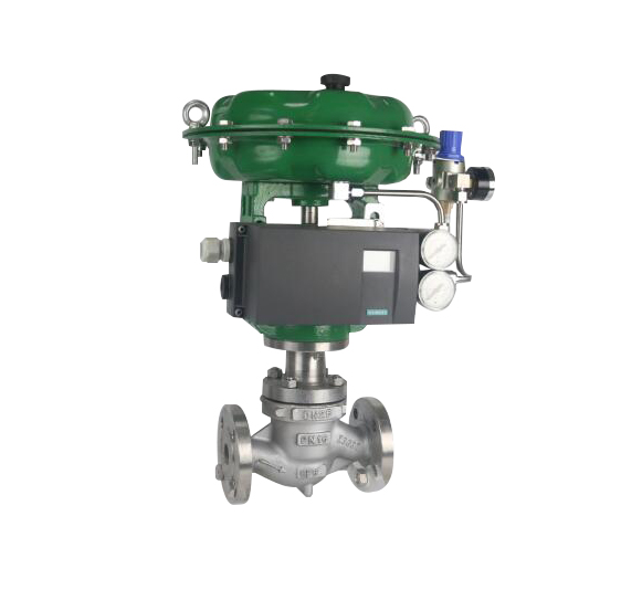
1.Summary of Pneumatic Single Seat Regulating Valve
Pneumatic single-seat regulating valve is composed of ZHA/B multi-spring pneumatic film actuator and top-guide through low flow resistance single-seat valve. It has compact structure, light weight, sensitive action, S-streamlined fluid passage, small pressure drop loss, large valve capacity, accurate flow characteristics, power distribution-pneumatic valve positioning or pneumatic valve positioner, which can realize the process. The automatic control of pipeline fluid medium is widely used to precisely control the parameters of gas, liquid, steam and other media, such as pressure, flow, temperature, liquid level, etc. The parameters are kept at a given value. It is a new generation of universal control valve products in line with IEC standards.
2. Main Technical Parameters of Executing Agencies
型 号 | ZHA-22 | ZHA-23 | ZHB-34 | ZHA-45 | ZHA-56 |
有效面积cm2 | 350 | 350 | 560 | 900 | 1600 |
行 程mm | 16 | 25 | 40 | 60 | 100 |
弹簧范围KPa | 20∼100(标准):40∼200;80∼240; 20∼60; 60∼100 | ||||
操作方式 | 普通型,带手动手轮操作型(侧装式,顶装式) | ||||
3. Electric-pneumatic valve positioner
Electrical valve positioner is the main supporting instrument of pneumatic actuator in industrial automation. It can be used to improve the linearity of valve position, overcome the friction force of valve stem and eliminate the influence of unbalanced force of regulating valve, so as to ensure that the valve position is proportional to the current signal of 0-10mA DC or 4-20mA from control system or regulating instrument. Achieve correct positioning. (Various models and specifications can be selected)
The company's electric-pneumatic valve positioner matching type (HEP-15 flameproof, HEP-17 intrinsically safe type). It can also be matched according to different requirements (ZPD2000 series, EP3000 series, EP4000 series, YT1000 series, YT2000 series, SIPART PS2 Siemens series and intelligent positioner series products)
4. Performance Indicators of Pneumatic Single Seat Regulating Valve
项目 | 指标值 | 项目 | 指标值 | ||||
基本误差% | 不带定位器 | ±5.0 | 始 | 气关 | 不带定位器 | 始点 | ±5.0 |
带定位器 | ±1.0 | 终点 | ±2.5 | ||||
回差% | 不带定位器 | ≤3.0 | 带定位器 | 始点 | ±1.0 | ||
终点 | ±1.0 | ||||||
带定位器 | ≤1.0 | 气开 | 不带定位器 | 始点 | ±2.5 | ||
终点 | ±5.0 | ||||||
死区% | 不带定位器 | ≤3.0 | 带定位器 | 始点 | ±1.0 | ||
终点 | ±1.0 | ||||||
带定位器 | ≤0.4 | 允许泄漏量L/h | 1×10⁻⁴×阀额定容量 | ||||
额定行程偏差% | ±2.5 | ||||||
Note: This product carries out GB/T4213-92 national standard.
允许压差 MPa
开关方式 | 执行器型号 | 弹簧范围KPa | 气源压力KPa | 需要附件 | 公称通径(阀座直径)mm | |||||||||||||||
20 | 25 | 40 | 50 | 65 | 80 | 100 | 150 | 200 | 250 | 300 | ||||||||||
(10) | (12) | (15) | (20) | (32) | (40) | (125) | (150) | |||||||||||||
气 关 | ZHA | 20∼100 | 140 | P | 6.4 | 5.94 | 3.34 | 3.34 | 2.14 | |||||||||||
ZHA | 20∼100 | 140 | P | 1.31 | 0.84 | 0.53 | ||||||||||||||
ZHA | 20∼100 | 140 | P | 0.51 | 0.33 | 0.21 | ||||||||||||||
ZHA | 20∼100 | 140 | P | 0.22 | 0.15 | 0.08 | ||||||||||||||
ZHA | 20∼100 | 140 | P | 0.06 | 0.04 | |||||||||||||||
气 开 | ZHB | 20∼100 | 140 | P | 4.46 | 3.09 | 1.98 | 1.11 | 0.71 | |||||||||||
ZHB | 20∼100 | 140 | P | 0.44 | 0.28 | 0.18 | ||||||||||||||
ZHB | 20∼100 | 140 | P | 0.17 | 0.11 | 0.07 | ||||||||||||||
ZHB | 20∼100 | 140 | P | 0.07 | 0.05 | 0.028 | ||||||||||||||
ZHA | 20∼100 | 140 | P | 0.03 | 0.02 | |||||||||||||||
Note: 1) P-valve positioner; R-pressure relay;
2) The allowable pressure difference is the maximum of P when the valve closes P2=0.
3) If the allowable pressure difference is not clear or the maximum working pressure difference is beyond the scope of the list, please contact us.

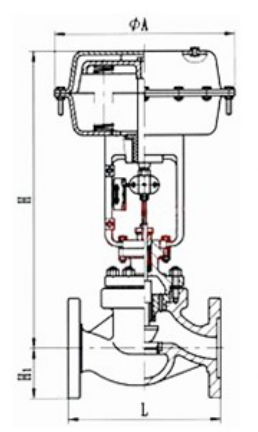
5.Configuration Dimension of Pneumatic Single Seat Regulating Valve
公通径(mm) | 20 | 25 | 32 | 40 | 50 | 65 | 80 | 100 | 125 | 150 | 200 | 250 | 300 | ||
L(mm) | PN1.6MPa | 181 | 184 | 205 | 222 | 254 | 276 | 298 | 352 | 410 | 451 | 600 | 670 | 735 | |
PN4.0MPa | 194 | 200 | 210 | 235 | 267 | 292 | 317 | 368 | 425 | 473 | 615 | 685 | 750 | ||
PN6.4MPa | 205 | 210 | 220 | 251 | 286 | 311 | 337 | 394 | 440 | 508 | 650 | 700 | 765 | ||
H1(mm) | PN1.6MPa | 53 | 58 | 68 | 73 | 80 | 90 | 98 | 108 | 123 | 140 | 168 | 203 | 230 | |
H1(mm) | PN4.0MPa | 53 | 58 | 68 | 73 | 80 | 90 | 98 | 115 | 135 | 150 | 188 | 223 | 255 | |
H1(mm) | PN6.4MPa | 63 | 68 | 75 | 83 | 88 | 100 | 105 | 125 | 148 | 170 | 203 | 235 | 265 | |
H(mm)≈ | 常温型 | 398 | 410 | 454 | 457 | 460 | 610 | 622 | 640 | 846 | 870 | 890 | 1203 | 1234 | |
高温型 | 548 | 560 | 604 | 520 | 627 | 790 | 807 | 850 | 1096 | 1130 | 1150 | 1523 | 1554 | ||
低温型 | -100℃ | H2 | 500 | 600 | 700 | ||||||||||
H≈ | 926 | 935 | 974 | 1082 | 1090 | 1240 | 1252 | 1275 | 1596 | 1620 | 1640 | ||||
ΦA(mm) | 285 | 360 | 470 | 620 | |||||||||||

